


Making sense of new technology
With any displacement measurement application, there is a
trade-off between the benefits and limitations of a
particular technology.Here, Micro-Epsilon compares four
types of non-contact displacement measurement
technolog
With any displacement measurement application, there is a
trade-off between the benefits and limitations of a
particular technology.Here, Micro-Epsilon compares four
types of non-contact displacement measurement
technologies, looking at the pros and cons of each
The use of non-contact displacement
technologies in precision
measurement is growing rapidly.
Customers need to measure more accurately,
to sub-micron or nanometre resolutions, and
against difficult surfaces or materials that
cannot be touched during measurements.
These materials include silicon, glass,
plastics, miniature electronic and medical
components, and food-based surfaces.
This growth has prompted development
of new technologies and the adaptation of
existing technologies to meet these new
measurement requirements and to improve
measurement accuracy and resolution. Noncontact
displacement sensors come in a wide
variety of shapes, sizes and measurement
principles. As well as eddy current and laser
triangulation sensors, capacitive and confocal
sensors are now popular, so it is critical that
engineers have a greater understanding of
the strengths and limitations of each
principle when selecting one for an
application.
Eddy Current Principle
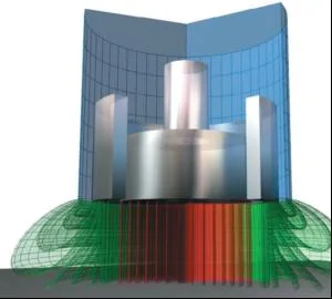
The eddy current measurement principle is
an inductive measuring method. A coil is
supplied with an alternating current, which
causes a magnetic field to form around the
coil. If an electrically conducting object is
placed in this magnetic field, eddy currents
are induced, which form an electromagnetic
field according to Faraday’s Induction Law.
The controller calculates the change in
energy transferred from the sensor coil to the
target material and converts this into a
displacement measurement. The advantages
are that this method can be used on all
electrically conductive, ferromagnetic and
non-ferromagnetic metals. The size of the
sensor is relatively small compared to other
technologies and the temperature range is
high due to the resistance measurement of
the sensor and cable. The technology is high
accuracy and is immune to dirt, dust,
humidity, oil, high pressures and dielectric
materials in the measuring gap.
However, output and linearity depend on
the electric and magnetic features of the
target. Therefore, individual linearisation
and calibration is required.Maximum cable
length is 15m and the diameter of the sensor
increases as the measuring range increases.
Capacitive Principle
With the capacitive principle, sensor and
target operate like an ideal parallel plate
capacitor. The two plate electrodes are
formed by the sensor and the opposing
target. If an AC current with constant
frequency flows through the sensor
capacitor, the amplitude of the AC voltage on
the sensor is proportional to the distance
between the capacitor electrodes. An
adjustable compensating voltage is
simultaneously generated in the amplifier
electronics. After demodulation of both AC
voltages, the difference is amplified and
output as an analogue signal. As the sensor is
constructed like a guard ring capacitor,
almost ideal linearity and resolution against
metal targets is achieved. The technology
offers high temperature stability, as changes
in the conductivity of the target have no
effect on the measurement. Capacitive
sensors can also measure insulators.
The technology is sensitive to changes in
the dielectric sensor gap and so operates
most effectively in clean, dry applications.
Cable length is relatively short due to the
effect of cable capacitance on the oscillating
circuit tuning.
Laser Triangulation Principle
In this principle, a laser diode
projects a visible point of light
onto the surface of the object
being measured. The backscattered
light reflected from
this point is then projected
onto a CCD array by a high
quality optical lens system. If
the target changes position
with respect to the sensor,
the movement of the
reflected light is projected
on the CCD array and
analysed to output the
exact position of the target.
Measurements are processed digitally in the
integral controller and then converted into a
scaled output via analogue (I/U) and digital
interface RS232, RS422 or USB. Benefits
include a small beam spot, long measuring
ranges are possible, the sensor operates
independent of target material, and a high
reference distance between sensor and target.
The method is limited by a relatively large
sensor design and a relatively clean optical
path is required for the sensor to operate
reliably. In addition, for direct reflecting
targets, specific sensor alignment/calibration
is required.
Confocal Principle
The technology works by focusing
polychromatic white light onto the target
surface using a multi-lens optical system.
Lenses are arranged in such a way that the
white light is dispersed into a monochromatic
light by controlled chromatic deviation. A
certain deviation is assigned to each
wavelength by a factory calibration. Only the
wavelength that is exactly focussed on the
target surface or material is used for the
measurement. Both diffuse and specular
surfaces can be measured.With transparent
materials such as glass, a one-sided thickness
measurement can be achieved along with the
distance measurement. Also, because the
emitter and receiver are arranged in one axis,
shadowing is avoided. Confocal offers
nanometre resolution and operates almost
independently of the target material. A very
small, constant spot size is achieved.Miniature
radial and axial confocal versions are available
for measuring drilled or bored holes.
Restrictions include the limited distance
between the sensor and target. In addition,
the beam requires a clean environment.
Key Selection Criteria:
Define clearly what it is that you need to
measure and why?
In what type of environment will the
sensor need to operate?
Are there space restrictions?
Custom versus off-the-shelf sensors?
When considering standard versus custom
sensors, improved sensor accuracy often
comes from re-calibration, intelligent
integrated sensor software, improving the
mechanical mounting or by manufacturing
the sensor from better components or
materials.
Compromising on resolution and
accuracy may save you time and money, but
will the sensor perform well enough in the
application?
Related posts
IPE Newsletter
IPE publishes a weekly eNewsletter, delivering a carefully chosen selection of the latest stories straight to your inbox.
Subscribe here