

Milestones in 3D measurement
The need for accurate measurement of objects with complex
geometries has challenged engineers and designers over
many decades. Here, Ralph Weir, CEO, Phase Vision, looks at
developments in three-dimensional measurement
The need for accurate measurement of objects with complex
geometries has challenged engineers and designers over
many decades. Here, Ralph Weir, CEO, Phase Vision, looks at
developments in three-dimensional measurement
Without accurate measurement
techniques, it is virtually
impossible to verify that items
have been manufactured to the required
tolerances, or to provide accurate data for
reverse engineering or virtual testing.
The 1950s saw the development of the first
two-dimensional co-ordinate measuring
machines (CMMs). The first three-axis
models appeared in the 1960s, with
computer control available from the early
1970s.
In the early days, mechanical probes were
fitted into a special holder on the end of the
quill. These probes were physically held
against the workpiece with the position in
space taken from a three-axis digital readout
or, in more advanced systems, logged into a
computer via a footswitch or similar device.
However, measurements were often
unreliable, as machines were moved by hand
and were prone to operator variability.
A further development was the addition of
motorised axes, meaning operators no longer
had to physically touch the machine.
Accuracy and precision also improved with
the invention of the electronic touch trigger
probe. As the probe touched the surface, the
stylus deflected, sending the X, Y, Z coordinate
information to the computer,
resulting in reduced operator error.
The next step forward was the optical
CCD probe, which moved like a mechanical
probe but was aimed at the point of interest
instead of touching the surface. The
horizontal information on the CCD is twodimensional
(XY) and the vertical position is
the position of the probing system on the
stand Z-drive.
Some newer CMM models have probes
that drag along the surface taking points at
intervals. This is often more accurate and
faster than conventional touch-probes.
However, while very accurate, the main
disadvantage with many CMMs is the
limited number of points that can be
measured, meaning a truly accurate
representation of a large or complex
component can take days, or even weeks.
CMMs can also only measure objects no
larger than their own dimensions. And with
any contact-based system, there is the risk of
surface damage, particularly on softer metals.
The next generation of scanning – noncontact
scanning – includes both laser
scanning and white light scanning. Both
methods allow thousands of points to be
taken and checked for size and position, with
a 3D image then created and transferred to
CAD software to create a working 3D model.
Non-contact scanning is clearly a must for
any material which is soft or delicate.
Introduced in the 1990s, laser scanning
enables rapid and complete measurement of
complex objects. It scans a small area at a
time by projecting a laser stripe which
generates a point cloud.
However, what it generates is effectively a
‘patchwork’ of scans, whose alignment is
difficult and often time-consuming.
Furthermore, results can be affected by
inconsistencies in laser focus, detune and
speckle, all of which mitigate against fast
scanning of larger areas, as well as variations
in distance between the scanner and the
object or created by different operators.
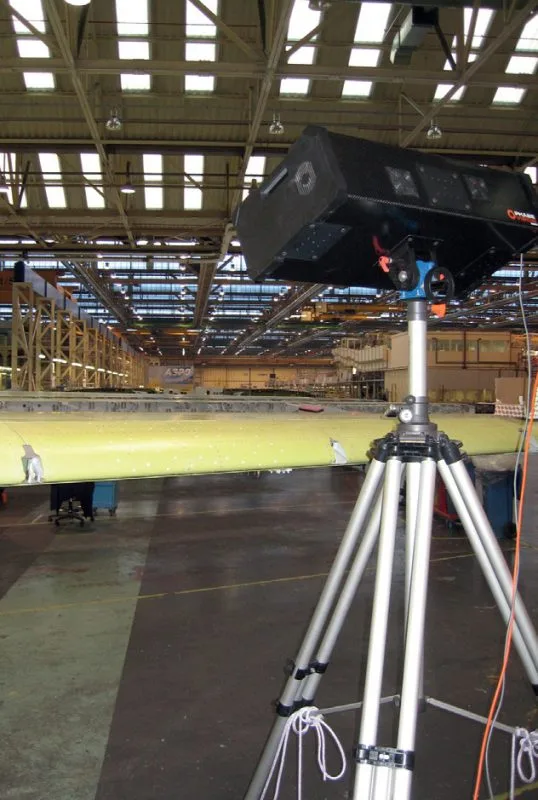
White light scanning seeks to combine the
best of both worlds in speed and accuracy
while being easy to use and allowing
scanning of large objects.
A white light scanner projects a
‘structured image’ – typically containing the
equivalent of hundreds or thousands of lines.
By projecting a series of these images, the
shape of the object can be calculated using
triangulation – just like a laser scanner, but
perhaps 10 or 100 times faster. An area of
metres can be measured in seconds – and,
because the scanned areas are enormous, the
need to align patches is greatly reduced.
The latest advances are overcoming many
of the challenges faced by the first white light
scanners: the issue of ‘stand-off distance’ –
the optimum distance between the scanner
and object; the need to see into holes; the
issue of shiny or reflective surfaces; and the
ability to operate in a range of environments
and lighting conditions.
All of these advances stem from
maximising the system’s ‘signal to noise ratio’.
While the issues could in theory be corrected
by either a brighter light source or a second
camera, the additional noise of a brighter
light or cost of a second camera make these
solutions unworkable. Instead, it is through
software enhancements that real
breakthroughs are being made – the latest
systems use sine waves, which are smoother
than stripes, eliminating the need for a
second camera, reducing the triangulation
angle, and enabling the scanner to see into
holes. And stand-off distance is no longer an
issue – the scanner can simply be moved
further away from larger objects.
It is this versatility and accuracy which is
seeing the new white light technology being
increasingly used in applications as diverse as
scanning of large aircraft wings, automotive
body panels and Powertrain components.
IPE Newsletter
IPE publishes a weekly eNewsletter, delivering a carefully chosen selection of the latest stories straight to your inbox.
Subscribe here