

Simple solutions secure savings
Compressed air systems can account for up to 15% of all
factory energy consumption, making them a prime target
for potential savings.Here, Steve Prueitt,product manager
air preparation with Parker Hannifin’s Pneumatics Div
Compressed air systems can account for up to 15% of all
factory energy consumption, making them a prime target
for potential savings.Here, Steve Prueitt,product manager
air preparation with Parker Hannifin’s Pneumatics Division
Europe, highlights simple methods of saving energy
Modern compressors are normally
highly efficient, with variable speed
controls being used to match
operating speeds and thus power
consumption to the demands of downstream
pneumatics equipment. So, unless
compressors are outdated or being operated
and maintained incorrectly, there is only
marginal room for improvement in this area.
By comparison, greater savings can be
achieved by considering the performance and
configuration of downstream systems. For
example, ensuring that leaks from badly fitting
tubes and fittings are prevented is an obvious
but often neglected task, and one that can have
a considerable impact on energy consumption.
Similarly, simple measures such as
ensuring that inline filters, typically in
dedicated FRL units, are cleaned or replaced
at appropriate intervals, can reduce the
problems both of pressure drop across each
filter and the resulting increase in energy
demand on the compressor.
A commonsense approach to basic
maintenance is both logical and essential. It
is, however, important to consider the design
and construction of the pneumatic
components being used throughout the
compressed air system as, collectively, these
can help to produce a major reduction in
energy consumption.
In particular, efficiency can be enhanced by
paying careful attention to the air flow paths
through valves, manifolds, fittings and filters,
to reduce pressure losses. As an example,
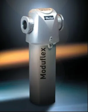
Parker’s Moduflex Extras coalescing and
adsorption filters have been developed using
computational fluid dynamic software, to
calculate the ideal flow paths through inlet
and outlet ports and across filter media under
a diverse range of operating conditions. This
has led to a number of improvements in
internal flow geometries. These include a new
bell mouth inlet design, which provides a full
and unrestricted path for air entering the
element chamber and reduces turbulence to a
minimum, plus a smooth inlet elbow that
efficiently directs air into the filter element.
The use of specially designed turning vanes
within the flow path channel the passage of
air in the most efficient manner, while flow
distributors and conical flow diffusers fitted
to each filter element ensure smooth air flow
through the element.
It’s worth recognising that the design of the
filter element will affect energy efficiency. The
latest elements use a deep bed pleated design,
with high performance borosilicate glass
nano-fibres to give a 96% voids volume and
the maximum possible surface for effective
filtration; typically, the available surface area
can be up to 450% greater than that of
traditional wrapped filter elements and around
200% more than standard pleated elements.
The overall effect is to reduce the velocity
of the air as it passes through the filter
element, giving excellent filtration efficiency,
high dirt holding capacity and low pressure
drop; the latter equates to a reduction in
energy consumption that remains at a low
level during the filter’s normal operating life.
The potential savings from these new
designs of filter can be substantial; for
example, compared with a traditional filter
unit of similar size and capacity, operating at
a differential pressure of 200mbar, a modern
deep pleated filter will produce energy
savings of almost 5000kW per annum, or
some 2100kg of CO2.
A similar approach can be taken to other
pneumatic components. For example, the latest
air preparation systems, such as Moduflex
Lite, combine a lightweight and corrosionresistant
injection moulded construction,
with optimised air flow geometry providing
greater efficiency with the opportunity to
reduce operating pressure and save energy.
Interestingly, this technology has two
additional benefits. Firstly, improved oil
atomisation allows lubricating oil mist to
travel far further along air lines without an
increase in operating pressure; typically this
can be more than 40m compared with the
normal maximum of around 15m. Secondly,
size for size, these products can be up to 45%
lighter and smaller than conventional units
while maintaining higher flow rates; this
enables engineers to replace older devices
with smaller, more affordable units that don’t
exceed tight budgets for capital expenditure.
For both old and new technologies, it’s
important not to forget the need to ensure
that all pneumatic components are sized
correctly for each application, as over-sized or
over-specified devices will be more expensive
to purchase and then cost more in terms of
ongoing energy consumption.
It’s a reasonable assumption that, for the
foreseeable future at least, the cost of
electricity to power factory systems will to
continue to rise; at best it’s unlikely to fall.
For some companies, counterbalancing this
through an increase in prices at the factory
gates may be an option; for most, however, it
will be cost savings through improved energy
efficiencies that will offer the best prospect of
maintaining profit margins, with savings in
the price of compressed air playing a vital
role in this process.
IPE Newsletter
IPE publishes a weekly eNewsletter, delivering a carefully chosen selection of the latest stories straight to your inbox.
Subscribe here