
|
Edward Lowton
Editor |


|
| Home> | Production Engineering | >Welding | >Fit for the future with smart robot welding technology |
Fit for the future with smart robot welding technology
21 March 2024
Innovative robot technologies - which now make automated welding economically viable even for small batch sizes - prompted high-precision measuring devices manufacturer Anton Paar to invest in a modern robotic welding system

AUSTRIA-BASED Anton Paar manufactures high-precision measuring devices for a wide range of industries. Up until now, all components of the measuring and control devices the company produces in Graz, have been welded by hand. This was because robotic welding systems were deemed uneconomical for small batch sizes between one and 400 pieces.
Ongoing sales growth, the increasing shortage of skilled workers in the domestic job market, and innovative robot technologies - which now make automated welding economically viable even for small batch sizes - prompted the high-tech company to invest in a modern robotic welding system.
"The shortage of skilled workers and ever-increasing quantities call for new solutions in production," said Dominik Santner, COO at Anton Paar. "The new robotic welding cell represents a huge step towards automation of our manufacturing. If we were to weld our process sensors manually like before, we would encounter huge difficulties achieving the planned quantities in the coming years."
Autonomous welding and a broad range of components
From the outset, the emphasis has been on system. Once set up, the welding system needed to be able to process a complete order from start to finish in a single pass. And the system had to be able to do this completely independently and without the intervention of welding specialists.
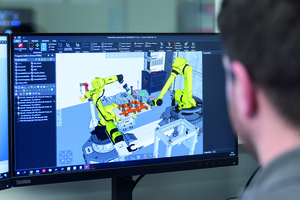
At Anton Paar, new welds are programmed offline - away from the welding system - rather than directly on the system, as is often the case. Rather than stopping ongoing welding work, welding continues during programming, increasing productivity. The welding technicians create the conditions for this by importing the CAD data of the measuring device components to be welded into the Fronius Pathfinder. Various joining scenarios are then tested and welding sequences are defined and optimised in the course of simulations.
Starting points, work angles of the welding torches, torch offsets in the corner areas, and all reorientations of the welding robot are all taken into account during these simulations. Pathfinder identifies instances where the robot range is exceeded, known as axis limits. By the software operators correcting the storage location of the workpiece and positioning it within arm's length of the welding robot, potential collisions between the torch and various component edges are avoided at an early stage.
Sources of errors identified in good time
If the track needs to be corrected, the affected teach points can be easily moved by dragging and dropping them. When the approach to the component needs to be changed, the specialists simply press Reset. The virtual robot then moves to the home position to start a new approach run. Under real-life conditions, operators would have to complete the time-consuming process of retracting the robot, moving it to the home position with the robot controller, and restarting the teaching process. By opting for the Pathfinder offline programming and simulation software, the experts at Anton Paar not only gain valuable time for welding work but also identify sources of error ahead of time.
Once a welding program has been set up in Pathfinder, it is translated by a so-called post-processor into the specific code of the Fanuc welding robot. It can then be transferred to the welding system via data transfer using a LAN connection.
Customised for Anton Paar
Anton Paar has access to custom workflows for welding its many different components, including the three main workflows.
Workflow 1: The components are welded on the turn-tilt positioner. A pallet loaded with components is removed from the pallet rack and temporarily stored on a pallet storage table. The handling robot then attaches a suitable gripper for picking up components, with six different ones being kept in what is known as a gripper station. Equipped with the gripper, the handling robot picks up the components and fixes them in a component-specific clamping device, which is already installed on the manipulator. The robot always removes one component at a time, which is then joined and returned to the pallet.
Workflow 2: The components are welded directly on the pallets, with the handling robot transporting the pallets from the pallet rack and positioning them in front of the welding robot. The handling and welding robots can then perform coordinated movements together during the welding process, enabling them to weld not just simple seam geometries but complex ones as well.
Workflow 3: The components are removed individually, positioned by the handling robot, and move in sync with the welding robot during welding. This is called coordinated motion.
In addition to the innovative Fronius welding technology, controls, tool center point (TCP) measurement, torch cleaning station, and enclosure, the robotic welding system consists of seven core modules that collaborate on the basis of software control. These consist of a handling robot, a welding robot, a turn-tilt positioner with forming gas unit, a pallet store with two racks, a gripper station, a torch changing system, and a pallet repository inside the system.
At the apex of welding technology
It was particularly important for Anton Paar’s welding specialists to be able to combine two welding processes for a component - for example, TIG for welding the root pass and MAG for welding the final run. However, the final choice of welding method depends on the welding calculations and the required resistance of the individual components.
"Our welding tests are the deciding factor in whether we use special processes such as CMT (cold metal transfer), PMC (pulse multi control), or LSC (low spatter control). The process we then decide on depends on the wall thickness of the component, on the type of weld, for example square butt or fillet weld, and on the required welding depths and micrographs," explained Daniel Moik, department manager for joining technologies. "We need about six or seven tests before we go into series production.If the heat input would be too great due to the nature of the material, the CMT cold welding process is of course suitable. If we want to boost productivity by increasing the welding speed, we look at PMC. If welding needs to be particularly low spatter, LSC might be a good choice, primarily because this prevents expensive rework."
Streamline fault detection
The welding data is recorded in the HMI. If the welding specialist finds a fault during the visual inspection, they can check the welding data record to see whether there have been any deviations from the limit values. Every component is subjected to a visual inspection (VI) as a matter of principle, and every tenth component undergoes a color penetration test (PT). This method can be used to detect cracks, pores, and lack of fusion of down to 1 µm. The PT-tested metal components are regularly subjected to micrographs at the end of the test cycle.
The innovative Fronius processes, a system concept that is both intelligent and flexible, and the ongoing potential to continue developing the robotic welding system ensure that Anton Paar’s sensitive, high-precision measuring devices will have perfect weld seams for years to come. The company’s welders simultaneously benefit from increased safety and protection of their health as they are shielded from the arc and its emissions by the enclosure and extraction system.
For more information:
Tel: +43 (7242) 241 3000


